Table of Content
- Introduction
- About ChargePilot
- Technical Setup
- Modbus Logic
- About the Modbus TCP/ IP Interface
- Register Tables
Introduction
The following Modbus register table gives an overview of the Modbus TCP/ IP connection between an Energy Management System (EMS) and ChargePilot’s Smart Charging Local Controller (LC). LC thereby always acts as a server for the Energy Management System. The LC acts as a client for the energy meter.

Figure 1: Modbus Interface Landscape

Figure 2: Modbus Interface Control Architecture
About ChargePilot
The following schematic shows the general role and outlines the supported interfaces of the Charging and Energy Management ChargePilot by The Mobility House. The LC is locally connected (over Ethernet/OCPP) to the operated charging stations and acts as their backend. More Information about ChargePilot can be found here.

Figure 3: ChargePilot Interface Landscape
Technical Setup
The Modbus interface is by default deactivated. If you are interested in using the feature, please contact your customer success manager at The Mobility House.
If enabled, you can connect to one of the ethernet ports on the Smart Charging Controller (Port A (charging stations) or Port B (internet connection)) and can be accessed via the IP and the Slave ID 1.
If connected to the customer's Internet and the same customer network as the Modbus client, the physical setup of ChargePilot is consistent with the normal pre-commissioning guidelines found on our website. If not using the customer’s internet, a port on the charger ethernet switch will need to be reserved to connect to the customer’s controller.
If you have any questions on the setup of ChargePilot, please contact our technical team.
Modbus Logic
Read Only Mode
If the Modbus interface is activated in Read only-Mode most registers can be read, but holding registers are not accessible (chapter Set Grid Values). All registers marked with a star in the table, are only available if the LC is connected to the ChargePilot meter.
Read/ Write Mode
If the Modbus interface is activated in Read/Write-Mode, also the holding registered are accessible.
The register 81XX sets absolute values for power (8192). While power settings are equally distributed on the connected phases, the current settings are to be set per phase.
Example: If a value of 30.000 is set, the maximum power of each phase is 10 kW.
By setting a value in Register 8200 “Grid Limit for all CPs in % of the physical maximum set by Administrator” the available power/current on each phase for the charging infrastructure will be reduced, to the set percentage.
Example: If the limit is 100 A per phase and a value of 60 is set, the maximum current per phase is 60 A.
Site Integrated Load Management
ChargePilot can also be operated with site integrated load management logic and Modbus. In this case, a meter is installed at the grid connection point to measure the building load and the residual power is distributed to the charging infrastructure. In this case, the Modbus interface can still operate in Read/Write-Mode. The additional limit set by the values of register 81XX is taken into account in addition to the restrictions given by the building load measured by meter.

Figure 4: Site Integrated Load Management
If Site Integrated Load Management load management logic is active, the Modbus interface can only be operated in Read Only-Mode!
Fallback Values
For the Modbus interface the following two fallback scenarios need to be considered
EMS Offline
In Read/Write mode (= external limits are received via the Modbus interface) the Modbus client (e.g. a EMS) sending limits becomes offline.
In this situation, a fallback value for the total site power will be set during setup of the interface. The logic will operate in fallback mode, after a configurable period (default is 30s), without receiving a signal on any of the holding register. The fallback value for the limit of the charging infrastructure and the interval can be adjusted during the implementation of your system.
Charger Offline
Whenever the charger loses connection to ChargePilot a predefined fallback value can be set individually for each charger. Whenever the charger appears offline in ChargePilot the charger can still charge with the fallback value. Furthermore, ChargePilot does not need to block/reserve the full capacity of charger. Example in the graphic below.

Figure 5: Fallback
About the Modbus TCP/ IP Interface
This document describes the behavior of the TMH Controller in case it is configured as Modbus TCP/IP server. In this mode, the TMH Controller is passively providing its metering data upon request to the devices which query the TMH Controller. Additionally, the client controller (customer’s controller) can write some configs in the Holding registers, if the feature is activated.
Special note for registers with a size of more than 16 bits:
Registers of such types are composed of standard 16-bit Modbus registers. Most-significant bits are located in registers with lower addresses, least-significant bits are stored in registers with higher addresses.
Example: Assume a virtual register (uint32) is placed at offset 0x1000. This register should reflect 2,293,828 operating hours. Address 0x1000 contains 0x23 and address 0x1001 contains 0x44. During transmission both registers are transferred in network byte order (Big Endian) as required by the Modbus specification, i.e. a “Read Holding Registers” for both registers shows up as 0x00 0x23 0x00 0x44 on the wire.
Register Tables
Total Live Values
The following table shows registers containing live data of the entire site.
Start address | End address | Start address | End address | Size | Input/Holding | Type | Unit | Description |
1 | 2 | 0x0001 | 0x0002 | 2 | Input | Int32 | 1W | Active power all CPs* |
5 | 6 | 0x0005 | 0x0006 | 2 | Input | Int32 | 1A | Current L1 all CPs* |
7 | 8 | 0x0007 | 0x0008 | 2 | Input | Int32 | 1A | Current L2 all CPs* |
9 | 10 | 0x0009 | 0x000A | 2 | Input | Int32 | 1A | Current L3 all CPs* |
11 | 12 | 0x000B | 0x000C | 2 | Input | uInt32 | 1V | Voltage L1-N** |
13 | 14 | 0x000D | 0x000E | 2 | Input | uInt32 | 1V | Voltage L2-N** |
15 | 16 | 0x000F | 0x0010 | 2 | Input | uInt32 | 1V | Voltage L3-N** |
17 | 18 | 0x0011 | 0x0012 | 2 | Input | uInt32 | 1 | cos_phi L1** |
19 | 20 | 0x0013 | 0x0014 | 2 | Input | uInt32 | 1 | cos_phi L2** |
21 | 22 | 0x0015 | 0x0016 | 2 | Input | uInt32 | 1 | cos_phi L3** |
23 | 24 | 0x0017 | 0x0018 | 2 | Input | Int32 | 1W | Active power site** |
25 | 26 | 0x0019 | 0x001A | 2 | Input | Int32 | 1VA | Apparent power site** |
27 | 28 | 0x001B | 0x001C | 2 | Input | Int32 | 1A | Active current L1 site** |
29 | 30 | 0x001D | 0x001E | 2 | Input | Int32 | 1A | Active current L2 site** |
31 | 32 | 0x001F | 0x0020 | 2 | Input | Int32 | 1A | Active current L3 site** |
Note: Holding registers are the read/write registers, Input registers are the read registers
*In case of some charger being offline, the capacity or fallback value of those chargers is added as to those values (assumed offline charging).
**Only available if the separate meter is connected to ChargePilot
Administration
The following table shows administration registers containing general information about the site.
Start address | End address | Start address | End address | Size | Input/Holding | Type | Unit | Description |
| 4106 | 4107 | 0x100A | 0x100B | 2 | Input | uInt32 | 1 | Amount of Charging stations |
4108 | 4109 | 0x100C | 0x100D | 2 | Input | uInt32 | 1 | Amount of connectors |
4110 | 4111 | 0x100E | 0x100F | 2 | Input | uInt32 | A | For sites with main and sub fuses: Limit of the first sub fuse For sites with only one fuse (no sub fuses): Limit of the main fuse |
4112 | 4113 | 0x1010 | 0x1011 | 2 | Input | uInt32 | A | For sites with main and sub fuses: Limit of the main fuse For sites with only one fuse (no sub fuses): N/A |
4114 | 4115 | 0x1012 | 0x1013 | 2 | Input | uInt32 | W | Current theoretical maximum power |
Note: Holding registers are the read/write registers, Input registers are the read registers
*Only available if the separate meter is connected to ChargePilot
Set Grid Values
The following table shows holding registers to set an external grid limit for the entire ChargePilot site.
Start address | End address | Start address | End address | Size | Input/Holding | Type | Unit | Description |
8192 | 8193 | 0x2000 | 0x2001 | 2 | Holding | uInt32 | 1W | Grid Limit for all CPs, equally distributed over all phases |
8200 | 8201 | 0x2008 | 0x2009 | 2 | Holding | uInt32 | 1% | Grid Limit for all CPs in % of the physical maximum set by Administrator |
Note: Holding registers are the read/write registers, Input registers are the read registers
*Only available if the separate meter is connected to ChargePilot
CP Live Values
The registers of the following section allows live data to be read for each connector. The following values are identical for connector 2 and so on with a gap of 256 (dec) or 100 (hex). So, the registers for connector 2 will start at 12560 or 0x3110, connector 3 at 12816 or 0x3210, and so on.
Order of the CP Live Value blocks
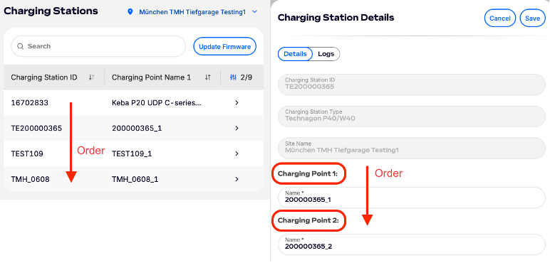
The blocks are ordered by ID of the connector (see first register of each CP Live Values block) = [Charger_ID][Connector_Number].
You can display the order in the ChargePilot UI go to: ChargePilot Dashboard -> Settings -> Site (search for site name) -> Sort by Charger ID. In case the charger has multible outlets/connectors, each connector will be a seperate block of CP Live Values. The connectors of one charger (Charger_ID) are ordered by Connector_Number (see Charge Point order in the Charging Station Details)
Start address | End address | Start address | End address | Size | Input/Holding | Type | Unit | Description |
12288 | 12303 | 0x3000 | 0x300F | 16 | Input | String32 |
| ID of Connector 1* |
12304 | 12305 | 0x3010 | 0x3011 | 2 | Input | uInt32 | 1W | Active power of Connector 1 inlet |
12306 | 12307 | 0x3012 | 0x3013 | 2 | Input | Int32 | 1A | Current L1 of Connector1 inlet |
12308 | 12309 | 0x3014 | 0x3015 | 2 | Input | Int32 | 1A | Current L2 of Connector1 inlet |
12310 | 12311 | 0x3016 | 0x3017 | 2 | Input | Int32 | 1A | Current L3 of Connector1 inlet |
12312 | 12313 | 0x3018 | 0x3019 | 2 | Input | uInt32 | 1V | Voltage L1 of Connector1 inlet |
12314 | 12315 | 0x301A | 0x301B | 2 | Input | uInt32 | 1V | Voltage L2 of Connector1 inlet |
12316 | 12317 | 0x301C | 0x301D | 2 | Input | uInt32 | 1V | Voltage L3 of Connector1 inlet |
12318 | 12319 | 0x301E | 0x301F | 2 | Input | uInt32 | 1W | Active power of Connector 1 outlet |
12320 | 12321 | 0x3020 | 0x3021 | 2 | Input | uInt32 | 1A | Current of Connector 1 outlet |
12322 | 12323 | 0x3022 | 0x3023 | 2 | Input | uInt32 | 1V | Voltage of Connector 1 outlet |
12324 | 12325 | 0x3024 | 0x3025 | 2 | Input | uInt32 | 1Wh | Total energy of Connector1** |
12328 | 12329 | 0x3028 | 0x3029 | 2 | Input | uInt32 | 0-4 | Status of Connector1
|
12330 | 12331 | 0x302A | 0x302B | 2 | Input | uInt32 | 1W | Active Discharging Power of Connector 1 |
12332 | 12333 | 0x302C | 0x302D | 2 | Input | uInt32 | % | SoC of EV connected to Connector 1*** |
12336 | 12351 | 0x3030 | 0x303F | 16 | Input | String32 |
| Session Id of Connector1 |
| 12352 | 12367 | 0x3040 | 0x304F | 16 | Input | String32 | ID Name (Vehicle ID, RFID) of Connector 1 | |
12374 | 12375 | 0x3056 | 0x3057 | 2 | Input | uInt32 | 1A | Current offer for Connector1 |
Note: Holding registers are the read/write registers, Input registers are the read registers
*[Charger_ID][Connector_Number]. In case the ID of Connector is longer than 32 characters the last characters of the Charger_ID are cut off.
**Consumed energy of an active charging session (4294967295 = no active charging session)
***Only available if provided by the charger (4294967295 = not provided by the charger)
Was this article helpful?
That’s Great!
Thank you for your feedback
Sorry! We couldn't be helpful
Thank you for your feedback
Feedback sent
We appreciate your effort and will try to fix the article